ABOUT DISSOLVED OXYGEN
Dissolved Oxygen Sensor Life Expectancy
PermalinkDownload FAQHow long should a DO sensor last in storage?
OxyProbes can be stored for several months from date of shipment with no appreciable change
in their performance or expected service life. After a few months, the sensors are still good but
they will probably need to have the membrane removed and refilled with electrolyte. Customers generally try to rotate stock so sensors are put into service prior to two months from shipment,
and this would be our recommendation for most customers.How long should a DO sensor last in actual service?
OxyProbe DO sensors exhibit a fairly predictable lifespan under continuous use. Typically they
need to be rebuilt every two years, depending upon the severity of the service. The higher the
temperature, the shorter the life; and, the longer the duration of exposure to elevated
temperature, the shorter the life. Maximum temperature advisable is 135°C.For example:
An OxyProbe may last 2 years autoclaved bi-monthly at 121°C for 30 minutes.
An OxyProbe may last 1 year autoclaved weekly at 121°C for 30 minutes.The actual service life attained will depend upon all other considerations, such as whether or not
the sensor is exposed to high pressure or mechanical vibration, whether or not the membrane is
punctured and media enters the inside, etc.. Since there are many variables and factors
involved in determining sensor life, an operator can best determine the life for their particular
vessel and set of conditions experimentally. By careful recording of when the sensors are
installed and a statistical analysis of typical life, one can determine the optimum number of
cycles.
There is a normal variance in sensor life and most operators of production vessels will search
out a timespan, perhaps 1-2 years, that gives them a maximum confidence in the ability to run a
cycle without failure. It is a helpful exercise to take the cost of a sensor rebuild and divide by the
number of cycles, then determine if the “cost per cycle” is justifiable for a particular product.For example, assuming a sensor rebuild costs £556 and you batch 26 runs per year:
If rebuilding once a year, the cost per run/per sensor would be about £21 (£556/26).
If rebuilding every 2 years, the cost per run/per sensor would be about £10 (£556/52).So, the decision to be made is if it is worth the extra £10 per run/per sensor to minimize the risk
of failure. Few customers run this many batches per year, and our experience has shown that
one rebuild every 2 years is a good average.What is the transmitter measuring?
PermalinkDownload FAQPolarographic DO sensors measure the partial pressure of Oxygen within the vessel. In order for the transmitter to convert the sensor’s current output to % saturation or ppm concentration, the transmitter must know the operating temperature and pressure of the sample media.
Why should DO sensors be calibrated after sterilization?
PermalinkDownload FAQCalibration: To optimize the readings, dissolved oxygen probes should be calibrated in the process media, after sterilization. This is due to several factors:
- Sterilization could alter the sensor output. The tension of the membrane against the cathode is an important factor in the sensor signal. The high temperatures of sterilization may cause the membrane to stretch. Calibrating after sterilization will account for any possible change in the sensor’s output.
- Many bioprocess applications involve aerating or sparging the vessel while applying an over pressure to the tank. This overpressure may affect the readings if not taken into account during the calibration.
- Since the membrane permeability is slightly different in air than in water and the ambient relative humidity of air is usually less than 100%, air calibrations can differ from aqueous calibrations by a very small amount.
In summary, when measuring dissolved oxygen as % saturation, the calibration should be performed under process conditions to minimize error and maximize accuracy and reproducibility.
What is the probe measuring?
PermalinkDownload FAQOxyProbes measure the partial pressure of oxygen. The partial pressure of Oxygen is dependent on the mixture of the gases and the pressure inside the vessel. Uncompensated variations in pressure can be a significant source of error. When reading % saturation or ppm, the operating pressure of the vessel should be entered into the transmitter if the process pressure is not the same as the calibration pressure. This number should account for elevation above sea level and/or any overpressure on the vessel. The pressure can be entered in mm Hg, inches Hg or bar.
How should I install a DO Sensor?
PermalinkDownload FAQA DO sensor must be at least 15° above horizontal to consistently function properly. DO NOT install DO sensors in a port perpendicular to the vessel wall. The liquid in the sensor contains small air bubbles. If not inclined slightly above horizontal, a bubble can adhere to the cathode where it will affect the sensor’s performance.
Close
ABOUT pH ELECTRODES
Why is the pH sensor stored dry – I thought this was typically not recommended for glass pH sensors?
PermalinkDownload FAQGlass pH sensors have a glass membrane that requires hydration to function properly. Therefore, the typical recommendation is to store pH sensors immersed in an aqueous buffer solution to ensure they are ready for use.
Broadley-James SingleSense® pH sensors, however, overcome the need for continuous hydration by using a special glass formulation that can rehydrate quickly without affecting sensitivity, enabling a long dry shelf-life.
Why do I see moisture inside the bellows of my sensor insertion assembly?
PermalinkDownload FAQGlass pH sensors have a porous ceramic junction that allows the reference electrolyte (a KCl solution) to contact the measured solution. During extended dry storage, the reference electrolyte may slowly leak from the junction by design, forming a visible drop of liquid inside the bellows.
- This electrolyte is non-cytotoxic (data available on request) and diffuses very slowly into the process fluid under normal conditions, as with any glass pH sensor.
- The presence of a small amount of liquid in the bellows is normal and does not indicate any damage to the sensor or create any additional exposure of the process to new materials.
How is the housing length determined?
PermalinkDownload FAQThe typical insertion length is calculated from the top of the threads to the furthest point, either the guard or the sensor tip.
How should I install a pH Sensor?
PermalinkDownload FAQA pH sensor must be at least 15° above horizontal to consistently function properly. DO NOT install sensors in a port perpendicular to the vessel wall. The liquid in the sensor contains small air bubbles. If not inclined slightly above horizontal, a bubble can adhere to the pH bulb where it will affect the sensor’s performance.
How do I achieve more accurate pH measurement?
PermalinkDownload FAQTo yield the most accurate pH measurement, it is important to compensate for temperature. Temperature has two significant effects on pH readings. The solution pH and the electrode output will both change at different temperatures. These two effects, either together or separately, can lead to errors in calibration, measurement and control.
What are the three most important things to remember during calibration?
PermalinkDownload FAQ- Always use fresh buffer. The pH of buffers will change quickly due to air, dilution and carry-over.
- After rinsing a pH electrode between buffers, blot the electrode dry, do not wipe it. Rubbing the electrode can build up a static charge, just like rubbing your feet on the carpet. This charge can prevent proper calibration. (If this happens, wait and let the electrode stand in solution so the charge can dissipate.)
- Always consider the effects of temperature on the measurements. Many pH measurements are temperature dependent. Please call us for a copy of our newsletter on temperature compensation and pH measurements.
How Should A pH Electrode Be Installed?
PermalinkDownload FAQAll pH electrodes (and DO sensors) can be mounted vertically, into a vessel headplate. Electrodes and sensors can also be installed on large vessels, through a side port. For side-entry installations, the probe must be at least 15° above horizontal to insure proper operation. Remember, there is liquid inside all pH electrodes and DO sensors. This slight 15° incline is enough to prevent a bubble from lodging itself at the tip of the sensor, preventing the sensor from operating properly.
How Should FermProbes Be Stored?
PermalinkDownload FAQNever store a pH electrode dry. The first choice for storing FermProbes is KCl solution. We recommend any concentration between 2.0 M and 3.8 M. Another good choice is buffer solution. A pH 4 buffer solution is best since it will keep longer, but pH 7 is also acceptable. If it is necessary to clean a FermProbe with acid, caustic, solvent or other cleaning solution, it is best to soak the electrode in KCl solution after cleaning and prior to use or calibration. This will re-condition the bulb and reference, extending the probe life and improving calibration accuracy.
What Are The Crystals On The Probe?
PermalinkDownload FAQDuring storage, salt crystals will often form on the electrode, around the soaker bottle. Sometimes the formation is so extensive there will be crystals under the soaker bottle and on the foam inside the box. This will not affect the performance, accuracy or life of the probe. Rinse off the crystals with water prior to use.
What Is The Shelf Life?
PermalinkDownload FAQFermProbes can be stored up to one year from date of shipment, with no appreciable change in their performance or expected service life. It is recommended to rotate inventory regularly and to follow FIFO (First-in, First-out) inventory management practices to avoid retention of aging sensors.
Why Is The Gel In The Probe Turning Brown?
PermalinkDownload FAQOver time, the high temperatures of sterilization will discolour the gel in a FermProbe. This is often referred to as caramelisation. It is normal, and in no way affects the performance of the electrode. This colour change can also be used to approximate the age of the electrode.
What’s Inside?
PermalinkDownload FAQThe gel in a FermProbe® is a non-toxic, USP grade, organic material. Other manufacturers may use different materials such as polyacrylamide. Please call us for more information or an MSDS.
Close
ABOUT pH TRANSMITTERS
What is the difference between a 2-wire and a 4-wire transmitter?
PermalinkDownload FAQ2-Wire vs. 4-Wire: A 4-wire transmitter is either powered by a 110V or 220V power supply. This allows direct activation of relays, pumps, solenoids, etc. However, in a hazardous environment, flammable or combustible vapors, gases or dust are present which could possibly ignite under certain circumstances. A 2-wire transmitter is loop-powered, which means it is powered by a low voltage, low current, DC power supply, typically 24V. A 4-20mA current is usually supplied by a distributed control system or other centralized data acquisition hardware and connected to the transmitter via 2 wires. A 2-wire transmitter does not directly control relays, pumps, etc., and will not spark if a malfunction occurs.
What is sensor interrogation?
PermalinkDownload FAQSensor interrogation is a feature of many transmitters today. It can be used to determine whether or not the sensor is working properly by sending a signal through the sensor and monitoring the response. The response will indicate whether the sensor is cracked, broken, clogged or otherwise not operating properly. The transmitter will then display a message indicating the sensor should be checked. For example, a remote operator overseeing a process running at a constant pH of 7 may not have any indication of problems. However, if the cable is shorted the transmitter will also display approximately pH 7. Without sensor interrogation, or physically checking the system, the operator may think the pH measurement is acceptable when in fact the electrode or cable is damaged, generating a false reading.
Close
DO MEASUREMENT
How do I change an OxyProbe II Membrane Cartridge?
PermalinkDownload FAQ There are two distinct types of 12 mm DO sensor cartridges: one for the traditional style sensor (for example, OxyProbe D140) and one for the newer style OxyProbe II sensors. Please make sure you received
the right membrane cartridge for your particular sensor design. The old and new membranes are not interchangeable and cannot be installed on the wrong sensor type. However, once opened, they cannot be
returned or re-sold so be sure to check the box label before opening it. If you have any questions, feel free to call us at +44 (0) 1525 862518.Important Notice:
The O2 electrolyte has an alkaline pH value of 13. Contact of electrolyte with the skin, especially the mucous membrane of the eyes, should be avoided. If such contact occurs, rinse the affected area thoroughly
with water. Get medical attention if adverse signs appear. An MSDS is available for download from our website if desired. Great care should be exercised when handling the sensor and changing the membrane. The internal glass cathode is very fragile and any impact can cause a crack or fracture which can permanently damage the sensor.Great care should be exercised when handling the sensor and changing the membrane. The internal glass cathode is very fragile and any impact can cause a crack or fracture which can permanently damage the sensor.
Because contact with the electrolyte is very likely during exchange of electrolyte or membrane body, the use of protective gloves and eyewear is recommended.Membranes are typically replaced after a single use in high-value processes, or after multiple uses in R&D, university, PD labs, etc. How many uses you might expect depends upon the process conditions. Visit our website FAQ section for more detailed information.
Membranes are typically replaced after a single use in high-value processes, or after multiple uses in R&D, university, PD labs, etc. How many uses you might expect depends upon the process conditions. Visit our website FAQ section for more detailed information.
Membrane Replacement Instructions
To replace the used membrane with a new one, or to remove, clean, and re-install the existing membrane, please follow these procedures:
- 1. Unscrew the cap sleeve from the shaft and carefully remove it from the sensor. Place the sensor down nearby in a safe place where it will not roll off or bump into anything that might damage the fragile glass tip of the cathode.
- Usually the membrane cartridge remains in the cap sleeve when the sleeve is removed from the sensor body. Tip it over and pour out the old electrolyte solution (remember it is pH 13). Carefully push on the flat face of the membrane with your finger or thumb to dislodge it from o-ring holding it in place within the cap sleeve. The cartridge should slide free of the cap sleeve.
- If re-using the old membrane, rinse it out with DI water using a squeeze bottle or other device to ensure all of the old electrolyte and byproducts are removed. Refill the cartridge slightly with OxyProbe electrolyte solution. Rinse it around and pour it out to flush out any remaining DI water.
- Check the o-ring on the sensor body, just above the threads where the cap sleeve attaches. If installing a new membrane, replace the o-ring with the one supplied with the membrane. If it is a re-use, inspect the o-ring and replace if necessary.
- Fill the membrane halfway with electrolyte solution, and give it a “tap” or “flick” of your fingernail to make any large bubbles rise to the top. *
- While holding the sensor in a vertical position, slide the membrane cartridge over the cathode assembly. The excess electrolyte will be displaced and this should be patted dry with a paper towel, kimwipe, etc.
- Take the steel cap sleeve and carefully slide it over the membrane cartridge, threading it onto the body until it is completely flush with the body.
- Rinse off any excess electrolyte that may have spilled, and dry the sensor with a paper towel, kimwipe, etc.
- Each time the membrane is changed the sensor should be polarized and calibrated before use. See the instruction manuals for your particular sensor and instrument, or visit our website “Documents” link.
* NEVER fill the membrane with electrolyte while it is lodged inside the cap sleeve. This causes excess electrolyte to be captured inside and can result in the rupture of the membrane during the autoclave cycle.
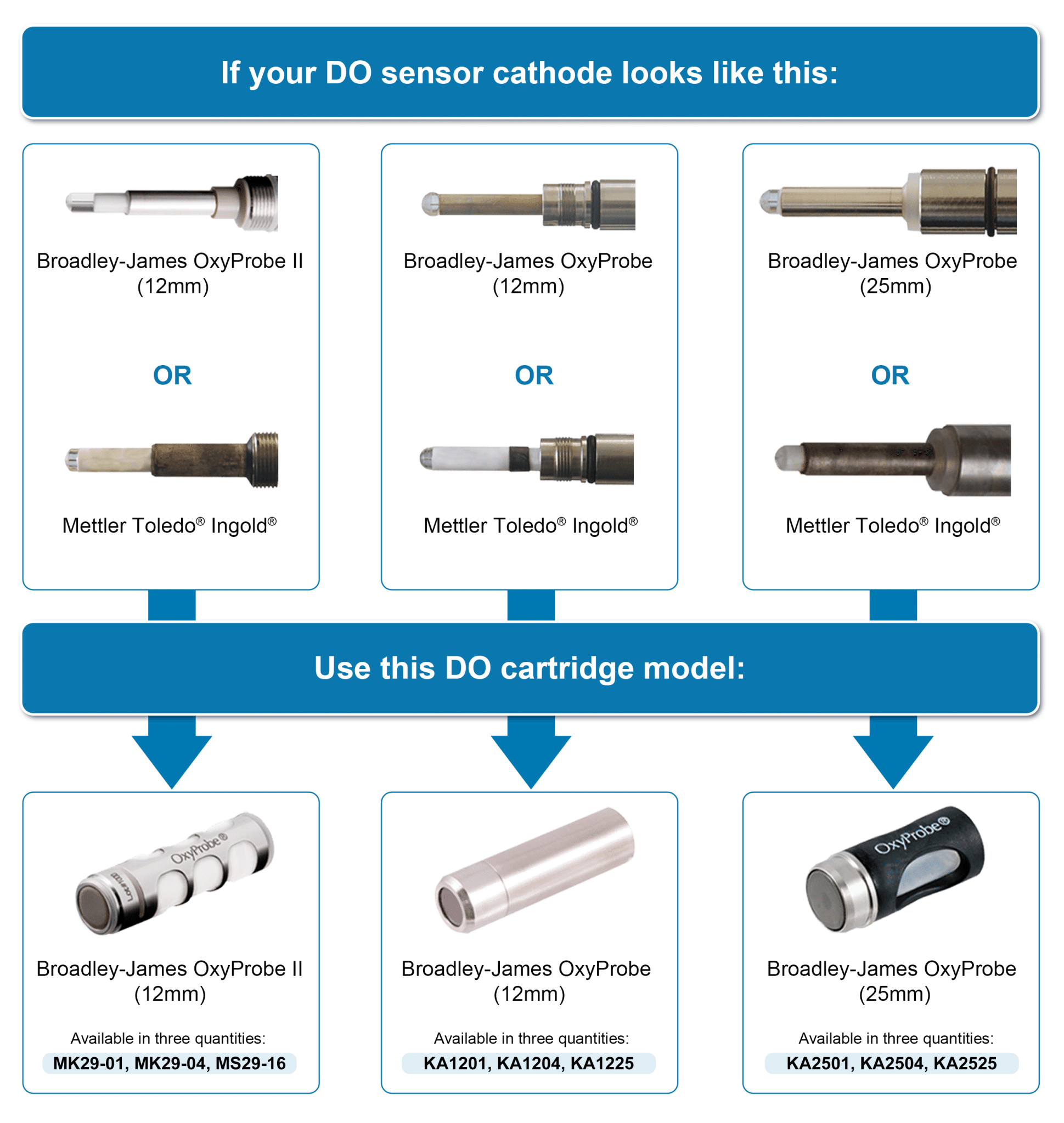
How do I choose the correct membrane cartridge for my dissolved oxygen (DO) sensor?
How do I change a membrane cartridge on a 19mm and 25mm Probe?
PermalinkDownload FAQStep 1
While holding the membrane cartridge upright (with opening up) in one hand, carefully pour the electrolyte from the bottle into the cartridge until approximately 75% full. Remove any entrapped air bubbles by tapping on the side of the membrane housing. Try not to spill any of the electrolyte and be certain to wipe off any excess electrolyte with a clean tissue from the outside surfaces of the cartridge.

Caution:The use of protective gloves and eyewear is recommended throughout the membrane cartridge refill and installation procedures.
Step 2
In one hand, grip the membrane cartridge, which has been properly filled with electrolyte, by the thumb and forefinger slots while holding the sensor body with the other hand as shown.

Step 3
While compressing the membrane cartridge with the thumb and forefinger, slide the cartridge over the anode / cathode assembly until the cartridge seats against the conical gasket. Release the pressure from the thumb and forefinger. Rinse lower portion of this subassembly with DI water to remove any excess electrolyte and blot dry with a clean tissue.

Step 4
The sensor body subassembly with the membrane cartridge in place is now ready for the installation of the stainless steel sensor sleeve.

Step 5
Slide the stainless steel sensor sleeve over the membrane cartridge, being careful not to knick the o-rings. Be certain that the mating threads of the sleeve and sensor body are free of any dirt or debris.

Step 6
Thread the stainless steel sensor sleeve onto the sensor body in the direction shown by the arrow. Be certain that the sleeve is flush with the sensor body so that no o-rings are visible. Do not overtighten. Hand tight is all that is necessary.

Note: Carefully inspect all o-rings and the conical gasket for any physical damage or excessive wear. Replace these items as needed or if there is any doubt as to their condition.
How do I change a membrane cartridge on a 12mm DO Probe?
PermalinkDownload FAQStep 1
While holding the membrane cartridge upright (with opening up) in one hand, carefully pour the electrolyte solution from the bottle into the cartridge until level is approximately 1/8″ (3 mm) from the top edge of the cartridge. Remove any entrapped air bubbles by gently tapping on the side of the membrane cartridge sleeve. Try not to spill any of the electrolyte solution and be certain to wipe off any excess electrolyte from the outside surface of the cartridge sleeve with a clean tissue.

Step 2
In one hand, grip the membrane cartridge, which has been properly filled with electrolyte solution, by the thumb and fingers while holding the sensor assembly with the other hand as shown.

Caution:The use of protective glovesand eyewear is recommended throughout the membrane cartridge refill and installation procedures.
Step 3
Gently slide the membrane cartridge over the cathode / anode assembly until the cartridge threads seat against the mating threads of the sensor assembly. Thread the membrane cartridge onto the sensor assembly until there is a flush fitting between the cartridge sleeve and the tube. With a proper fit, the sealing o-ring should no longer be visible.

Note: The use of protective gloves and eyewear is recommended throughout the membrane cartridge refill and installation procedures.
Step 4
Rinse the front portion of the sensor assembly with clean tap water and blot dry with a clean tissue to remove any excess electrolyte. The sensor is now ready to be polarized.

Note: Carefully inspect o-rings for any physical damage or excessive wear. Replace as needed or if there is any doubt as to their condition.
How do I select a sensor for benchtop vessels?
PermalinkDownload FAQTypically a benchtop application is less than 5L, and uses a glass vessel or flask. Usually the entire vessel can be placed or wheeled into an autoclave for sterilization prior to a run. Not only is there a range of different vessel sizes used in benchtop bioprocess applications, but also the volume of the media in the vessel will often change during the process. Accordingly, the sensors for benchtop vessels are available in a wide variety of lengths. The operator must choose a sensor length that ensures the sensor tip is submerged at all times during operation. Some sensor models have been configured to thread directly into the headplate and various access ports found on small vessels. Detachable cables and other design features allow these products to withstand the demands of autoclaving requirements.

What are the effects of Pressure on Steam Temperature?
How Do I test My OxyProbes?
PermalinkDownload FAQPurpose for test:
Dissolved oxygen membrane cartridges contain an oxygen-permeable, polymer membrane, which is impermeable to liquid. Improper storage or accidental handling of the DO sensor or membrane cartridge can damage the polymer membrane. A hairline scratch, slight abrasion or any tear of the polymer membrane may render the cartridge inoperable. Often the damage may not be visible to the naked eye.
STEP 1. VISUAL EXAMINATION
Remove the membrane cartridge from its storage vial or from the dissolved oxygen sensor. Be careful not to scratch or abrade the polymer membrane portion of the cartridge.Visually inspect the outer surface polymer membrane for scratches, scars, abrasions or tears.

STEP 2. PLUNGER “READY” POSITION
Install the nosepiece onto the syringe and retract the plunger of the membrane tester to the “ready” position as shown below.
STEP 3. MEMBRANE CARTRIDGE INSTALLATION
Insert the tip of the membrane tester into DI water to lubricate it before installing the membrane cartridge as shown below. Avoid excessive force.
STEP 4. APPLYING PRESSURE TO THE MEMBRANE CARTRIDGE
Slowly compress the plunger until the membrane cartridge bladder slightly protrudes from the thumb and forefinger slots of the cartridge housing.
STEP 5. MEMBRANE CARTRIDGE TEST
Place membrane tester with the membrane cartridge into a beaker of DI water as shown. Make certain the front of the membrane cartridge is completely submerged.
STEP 6. ASSESSING DAMAGED MEMBRANE CARTRIDGES
While maintaining a slight pressure on the plunger to keep the bladder extended, slowly rotate the test assembly in the water.
Look for any signs of air bubbles which indicate a damaged membrane or bladder. Refer to the two illustrations for typical examples of air leaks found when the membrane has been damaged.
- NOTES:
A good membrane will not permit any air to escape from the membrane cartridge when this test is properly performed. - Replace cartridges which show any signs of air leakage, whether flowing from or clinging to the surface of the polymer membrane.
- New membrane cartridges should always be kept in their individual storage vials until required for service. Avoid unnecessary handling. Membrane cartridges installed on a dissolved oxygen sensor should be protected during non-use.
Testing the Cathode
PROCEDURE:
Refer to drawing below. Using a multimeter with the test leads attached to as shown, V ohms and COM connect one lead to a small piece of aluminum foil and the other lead to the WHITE (cathode) lead of the sensor cable. Gently touch the tip of the platinum cathode to the aluminum foil being careful not to damage the surface of the cathode. With the multimeter selector switch in the ohms position, the readout should indicate a direct short or “zero” ohms. This measurement verifies proper electrical continuity between the tip of the platinum cathode, the connectors, and the cable.RESULTS:
A reading which is significantly different than “zero” ohms could indicate a faulty cable, cable connector, sensor connector, and/or internal fault to the cathode. Replace the cable assembly and repeat the test measurement. If the correct reading is not achieved, replace the sensor connector. If the correct reading is not achieved after these two steps, the sensor should be returned to the factory for further service.
PROCEDURE:
Refer to drawing below. Using a multimeter with the test leads attached to V ohms and COM as shown, connect one test lead to the RED (anode) lead of the sensor cable. Gently touch the tip of the other test lead to the outer surface of the silver anode. With the multimeter selector switch in the ohms position, the readout should indicate a direct short or “zero” ohms. This measurement verifies proper electrical continuity between the anode, the connectors, and the cable.RESULTS:
A reading which is significantly different than “zero” ohms could indicate a faulty cable, cable connector, sensor connector, and/or internal fault to the cathode. Replace the cable assembly and repeat the test measurement. If the correct reading is not achieved, replace the sensor connector. If the correct reading is not achieved after these two steps, the sensor should be returned to the factory for further service.PROCEDURE:
Refer to drawing below. Using a multimeter with the test leads attached to V ohms and COM as shown, connect one test lead to the BROWN (RTD) of the sensor cable and the other test lead to the BLACK (RTD) of the sensor cable. With the multimeter selector switch in the ohms position, the readout should indicate between 27.0 k ohms to 22.0 k ohms at room temperature (20 to 25°C) or other appropriate resistance value depending upon the ambient temperature. This measurement verifies the internal thermistor is functioning properly.RESULTS:
A reading which is significantly different than the values given above could indicate a faulty cable, cable connector, sensor connector, and/or internal fault with the thermistor. Replace the cable assembly and repeat the test measurement. If the correct reading is not achieved, replace the sensor connector. If the correct reading is not achieved after these two steps, the sensor should be returned to the factory for further service.Close- NOTES:


pH MEASUREMENT
How do I test my pH electrode?
PermalinkDownload FAQpH Electrode Test Procedure
The purpose of this test is to determine if a pH electrode is functioning within acceptable limits. The asymmetry potential (A.P) and slope (efficiency) can be used as guidelines to judge an electrode’s performance. Typically an electrode is replaced when the A.P is greater than ±20 mV and/or the slope drops below 91%. Consideration should also be given to the electrode’s speed of response. Please follow this step-by-step procedure to determine the performance of an electrode. Required test equipment includes 7.00 and 4.01 pH buffer solutions with a pH meter that has an mV readout.
- Set the pH/mV switch on the pH meter to the mV position.
- Connect a shorting plug to the input on the pH meter, or connect a precision mV generator with a 0 mV input. Adust the standardize/zero control on the pH meter for a reading equal to 0.0 mV.
- Disconnect the shorting plug/precision mV generator, and connect the electrode that will be tested.
- Rinse the electrode thoroughly with DI water to remove all traces of storage solution, process medium, or previous test solution. Thoroughly rinse the electrode after each buffer test to prevent carry over contamination of the pH buffer solutions. Gently blot the electrode on a soft tissue to remove the excess rinse water. Do not rub the bulb since it can cause a static charge build-up.
- Insert the electrode and the ATC (automatic temperature compensator) in 7.00 pH buffer solution. Allow 30 seconds for the electrode/ATC to reach thermal equilibrium with the buffer solution. Record the polarity and the mV reading. This is the asymmetry potential of the electrode.A perfect electrode would have an A.P equal to 0 mV, but most electrodes read between ±30 mV.Note: If the meter does not have an ATC, place a thermometer along with the electrode in the 7.00 pH buffer solution. Allow 30 seconds for the pair to reach thermal equilibrium with the buffer. Adust the temperature setting on the meter to correspond with the thermometer reading. Record the polarity and the mV reading to determine the A.P
- Repeat Step 4, and insert the electrode and the ATC in a 4.01 buffer solution. Allow 30 seconds before recording the mV reading.
- Determine the mathematical difference between the two mV readings. This is the electrode’s span.
- Divide the electrode’s span by the theoretical span of 176.9 mV (at 25ºC) and multiply by 100. This determines the slope of the electrode.
Note: For best results, the pH buffer solutions should be used at 25ºC. Otherwise, record the temperature of the buffer and determine the temperature adjusted pH with the temperature coefficient charts printed on the buffer container.
Example: Download this calculator in an Excel file
Reading in a 7.00 pH buffer solution: -7.4 mV Reading in a 4.01 pH buffer solution: +164.6 mV
Asymmetry Potential = -7.4 mV Span = +164.6 – (-7.4) = 172.0 mV
Slope = Span = 172.0 mV
Theoretical Span 176.9 mV X l00 = 97%
Electrode Test Results:
Reading in a 7.00 pH buffer solution: ___________ mV (max/min range ±40 mV)
(Asymmetry Potential)Span = ___________mV – ___________mV = ___________mV (min 150.4 mV)
(Reading in 4.01 pH) (Asymmetry Potential)Slope = Span ÷ Theoretical Span (176.9 mV) X l00 = _______________% (min 85%)
Date Tested:______________ Initial:_______ Identification:_________________________________
(Electrode P/N, Vessel Location/No.)All electrodes have a finite life, and should be tested from time to time to determine acceptable performance.
TRIS Buffers – What electrodes can I use?
PermalinkDownload FAQTRIS buffers are used by biochemists to control pH in the physiological range (about 7 to 8 pH) because phosphates cause undesirable side reactions with the biological substances in their test samples.
However, when pH measurements are to be made on these solutions, another type of “undesirable side reaction”, involving the pH electrode system, must be recognized. The common Silver-Silver Chloride reference electrode used with most combination pH electrodes has a Potassium Chloride salt-bridge which is saturated with Silver Chloride. This salt-bridge system works well in most samples, but not in biological samples containing proteins or related materials. The quite low concentration of Silver ion (about 0.0001 M) is sufficient to react with proteins and produce an insoluble precipitate in the porous liquid junction structure of the electrode and thus cause errors in pH measurement due to the development of substantial “liquid junction” potentials across this plug of precipitate.
This problem can be avoided quite simply by using an electrode with a calomel reference internal element, or a “double-junction” design. Either reference internal cell is contained in its own glass tube structure within the salt-bridge, and the Potassium Chloride solution does not contain heavy metals. Thus, none of the undesirable precipitates form, the reference junction remains unplugged, and the liquid junction potential remains negligible.
Dr. John E. Leonard, Broadley-James Corporation
10/81
Accurate pH Measurements in Tris Buffer Solutions
Introduction
Tris, or tris (hydroxymethyl) aminomethane, has been widely used as a pH buffer in biological media for approximately thirty-five years. The almost ideal characteristics of this physiological buffer account for its popularity. Tris is not hydroscopic is easily dissolved in water, and is available in high purity. It does not precipitate calcium salts, is stable in solution at room temperature for months, and does not appear to inhibit many enzyme systems. During the late ’60s, it was reported that incorrect pH readings were obtained when the reference electrode used to measure the pH of tris had a linen fiber liquid junction. This problem, though easily eliminated, has raised a number of questions concerning the proper reference for use with tris buffers. Additionally, because of the chemical and physical properties of tris buffers, improper use may lead to erroneous pH measurements. The purpose of this bulletin is to point out the possible sources of error and to recommend the most appropriate electrode system for pH measurement when tris buffers are used.
Effect of Chemical & Physical Properties of Tris Buffers on pH
Table I contains compositions, buffer values, dilution values, and an approximate temperature coefficient of tris buffer over its practical buffer range (pH 7 to 9). The data in Table I indicates that tris in the pH range frequently used for physiological measurements (pH 7 to 7.5) does not have a large buffering capacity. Therefore, caution should be exercised when using tris buffers to control sample pH. The rather large temperature coefficient of tris (- 0.028 pH/°C) also warrants consideration. For example, if a tris buffer is used to standardize a meter, and the tris temperature is 20°C, using the pH value at 25°C will result in an error of

Clearly, for best results, the temperature pH dependency must be used when standardizing with tris. It directly follows that when tris is used to control the pH of a sample, the degree of control will be dependent on sample temperature. If the sample temperature varies by 2°C, the pH control varies by approximately 0.06 pH units. The desired pH control will dictate the maximum allowable temperature fluctuations.
Tris is a primary aliphatic amine and can react with some samples. When tris is used to control sample pH, the possibility of a reaction with the sample should be considered. For example, tris forms a stable complex with Silver ion. The presence of Silver ion in the sample may rule out using tris to control the pH of the sample.
PH Measurements Using Tris Buffers
- Use an electrode pair or combination with a ceramic or sleeve-type junction.
- Calomel or Silver/Silver Chloride type references will be satisfactory for most measurements. However, the possibility of introducing heavy metal ions (Ag+, Hg22+) should be considered. This problem is less likely to occur when a calomel reference is used due to the lower solubility of Mercurous Chloride versus Silver Chloride. Introducing heavy metals into the sample can be eliminated by using a double junction system with either reference.
- Tris buffers should be prepared from high purity tris and HCl using C02-free distilled or deionized water.
- The pH of tris buffers is temperature dependent. For most accurate work, all solutions should be thermostated.
Table 1
COMPOSITIONS, BUFFER VALUES ß, AND DILUTION VALUES ApH I/2,
OF SOME TRIS BUFFER SOLUTIONS AT 25°C50mL 0.1 M tris (hydroxymethyl)-aminomethane, x mL 0.1 M HCI,
Diluted to I00mL dpH/dt = – 0.028 unit deg.-1; I = 0.001XpH x β ApH I/2 7.00 46.6 – -0.02 7.10 45.7 0.010 7.20 44.7 0.012 7.30 43.4 0.013 7.40 42.0 0.015 7.50 40.3 0.017 -0.02 7.60 38.5 0.018 7.70 36.6 0.020 7.80 34.5 0.023 7.90 32.0 0.027 8.00 29.2 0.029 -0.02 8.10 26.2 0.031 8.20 22.9 0.031 8.30 19.9 0.029 8.40 17.2 0.026 8.50 14.7 0.024 8.60 12.4 0.022 8.70 10.3 0.020 -0.01 8.80 8.5 0.016 8.90 7.0 0.014 9.00 5.7 – -0.01 a) From R.G. Bates, Determination of pH Theory and Practice, 2nd ed., p. 161, John Wiley and Sons; Inc., Now York, 1962.
References
- R. G. Bates, Part 1. Physiochemical Properties of Amine Buffers, Amino Buffers for pH Control. Ann. N.Y. Acad. Sci., 92,341 (1961).
- R. E. Benesch and R. Benesch, The Stability of the Silver Complex of Tris (Hydroxymethyl) Aminomethane, J. Am. Chem. Chem Soc., 77,2749 (1955).
- J. H. Fossum ot. al., Tris (Hydroxymothyl) Aminomethane as an Acidimetric Standard, Anal. Chem. 23,491 (1951).
- W. F. Koch et. al., Tris (Hydroxymethyl) Aminomethane – A Primary Standard?, Talanta 32,637 (1975).
- Sigma Technical Bulletin 106B (3-72), Sigma Chemical Go., St. Louis, MO.
Suggested Readings
- N. E. Good et. al., Hydrogen Ion Buffers for Biological Research, Biochemistry 5,467 (1966).
- R.A. Durst and B. R. Staples, Tris/Tris HCI: A Standard Buffer for Use in the Physiologic pH Range, Clin. Chem. 18,206 (1972).
- R. G. Bates ot. al., pH Standard for Bood and Other Physiologic Media, Clin. Chem. 7,292 (1961).
Do you have a datasheet for FermProbe Wetted Materials?
PermalinkDownload FAQ
The FermProbe Double Junction Reference System
All FermProbes have two built-in electrolyte chambers that act to protect and isolate the sensitive inner AgCl reference half-cell. This “double junction”, dual-chamber design effectively prevents the most common failure modes of pH electrodes in biopharmaceutical applications.
Only the inner, smaller chamber contains silver ions in the electrolyte. The larger chamber is free of silver ions. This design prevents silver ions from coming into contact with proteins or sulfide ions in the sample media. Reactions between proteins or sulfide ions and the silver ions will cause the formation of substances that will clog the outer ceramic reference pin junction.
All pH and Redox FermProbes have this double junction reference system as a standard feature to insure maximum service life over the widest range of operating conditions.
Wetted Material List for all FermProbes
(A) Glass Outer Body: Potash soda lead glass
(B) Glass Bulb: Silica glass made with small percentages of alkali elements. The exact formulation is proprietary and confidential.
(C) Porous Ceramic Liquid Junction: Silica plus complex mineral compounds fired at high temperature to form an inert, porous ceramic matrix. The exact formulation is considered proprietary and confidential.
(D) Internal Electrolyte Gel:
- Potassium Chloride, 3.8 M
- Cellulose thickening agent, USP Grade
(E) All wetted materials are compliant with applicable FDA regulations.
Why is my FermProbe turning brown?
PermalinkDownload FAQThe longer the electrode is exposed to high temperatures (above 100 degrees °C) the darker it becomes. Likewise, the higher the temperature, the darker the colour. This is normal. If the electrode can be calibrated, it’s OK to use it.

Are there different types of ports?
PermalinkDownload FAQThe electrode housing is designed to hold and protect the pH electrode while inserting it into the bioprocess vessel. There are various types of side entry ports and different groups of housings to fit each port type. The size and make of the port must first be identified in order to narrow the selection process.
The most common types of entry ports found on pilot and production scale vessels are as follows:
Standard 25mm Side Port

Found on nearly all vessels other than those manufactured by B. Braun Biotech. The port bore is 25 mm i.d. and the housing o-ring seals to the inside of the port. The housing is then secured to the port by a threaded retainer ring. The port is installed at a 15° angle for better electrode performance. See the cutaway drawing to the right for typical installation dimensions.
B. Braun Biotech 25 mm Safety Port

Found exclusively on vessels manufactured by B. Braun Biotech. This style of port is longer than the standard port and needs a special housing to fit correctly. (Note: the port opening on newer tanks is 30 mm i.d. and the port narrows down to 25 mm i.d. at the critical point where the housing o-ring seals to the inside wall of the port.) Again, the port is installed at a 15° angle for better electrode performance. See the cutaway drawing to the right for typical installation dimensions.
How do I match electrodes to housings?
PermalinkDownload FAQHousings and FermProbe® pH electrodes are offered in a variety of lengths. This enables fermentation operators to select the optimum insertion length for the application at hand. The housing ordering information box lists the suitable electrode models and lengths for each particular housing style.
There is another way to match electrodes to housings. Each housing length is given a letter classification, i.e. “A”, “B”, “C”. Each electrode length is given a similar letter classification. Any Class “A” pH electrode will fit any Class “A” housing listed in this catalog. Similarly, any Class “B” electrode will fit any Class “B” housing. By matching the classifications, the electrode and housing will match.
The class information is found in the ordering information box for any electrode or housing in this catalog. If the class letters are the same for any electrode and housing then the two can be used together. See the illustrated example below:
For a Perfect Match Every Time
- Choose a housing for the vessel and application.
- Note the class of the housing (i.e. A, B) in the ordering information box.
- Choose a style and model of electrode (see opposite page).
- Find the class of electrode that matches the class of the chosen housing.
Example

Why would I choose a longer electrode length?
PermalinkDownload FAQSometimes the tank wall can become coated with a thick layer of viscous material that does not mix well with the rest of the media. If the pH sensing bulb of the electrode is located just a couple of inches inside the tank wall, the bulb might be smothered by this viscous layer. Subsequent pH readings may not be representative of the bulk of the media circulating in the rest of the tank. In the illustration at the right, the pH electrode’s bulb is trapped in this slow moving viscous layer near the tank wall. The electrode is only measuring the pH of this layer.

Bulb of electrode is trapped in thick viscous layer near the wall of the tank. Bulb of electrode is trapped in thick viscous layer near the wall of the tank.
The solution to this problem described above is to choose an electrode and matching housing that extends further into the tank. This will position the pH sensing bulb away from the tank wall and place it closer to the circulating media further inside the tank. The subsequent pH measurements will be much more representative of the circulating media. In the illustration to the right, the electrode and housing protrude past the viscous zone and into the area of well stirred and circulated media within the production tank.A longer sensor and housing extend further into the tank. The sensing bulb of the pH probe is past the viscous zone. How should I clean a FermProbe?
PermalinkDownload FAQ

FermProbe® Cleaning Procedures
Remove Bulb Coating
- Protein Deposition
- Warm water bath with dish detergent
- Warm water bath with enzyme detergent (i.e. Terg-A-Zyme®)
- Scrub bulb and rinse
- Inorganic Scale Deposits
- Dip only the bulb of the electrode into 0.1N hydrochloric acid
- Rinse
- Organic Oil or Films
- Clean with acetone and rinse
- Rehydrate in KCl solution for 4 hours
Remove Junction Coating
Plugged or Dry Junction
- Remove observed contaminant
- Place in KCI solution, 2M or stronger
- Heat slowly to 50ºC
- Let cool to room temperature
- Repeat 2 or 3 times if necessary
Proper Storage When Not In Service
Keep Bulb Hydrated
- Store in 2M KCl or stronger
- Use soaker bottles or storage containers
- Do NOT use D.I. water for storage
Cleaning
FermProbes which are physically intact can often be restored to an improved level of performance by one of the following cleaning procedures:
- General: It is good practice to wash the tip of the electrode with a solution made from dish soap and/or enzyme detergent and warm clean water. An alternative is to use a caustic, such as Sodium Hydroxide, or CIP 100, typically a diluted solution with a pH of around 12 to 13 pH. Use a soft toothbrush or a clean soft cloth wetted in the solution to carefully scrub the tip of the electrode. Thoroughly rinse the electrode tip with distilled or D.I. water and soak in KCl solution, 2M or stronger, for a minimum of 30 minutes before recalibration or returning electrode to service. Do not store in distilled or D.I. water.
- Inorganic Deposits: Try to dissolve deposit by immersing the electrode bulb in 0.1N Hydrochloric acid for a few minutes followed by a thorough rinse with D.I. or clean tap water. Then proceed with the general cleaning in Step 1 of this section.
- Organic Oil, Grease Films or Fingerprints: Wash electrode bulb with the solution in Step 1 of this section. Wash the tip with acetone. Follow with the general cleaning procedure in Step 1 of this section. Note: Depending on the extent of the oil and/or grease contamination, the electrode may be damaged beyond recovery.
- Plugged or Dry Ceramic Liquid Junction: Try at least one of the previous 3 steps in this section. Place the electrode in KCI solution, 2M or stronger. Heat slowly to 50ºC then let cool to room temperature. Repeat as necessary.
General Practice Information
- Try to always store the electrode in KCl solution, 2M or stronger. Buffer solution of pH 4 is also acceptable. Do NOT store an electrode in distilled or D.I. Water.
- Cracked or broken electrodes are not repairable.
- Inspect cable for cuts or other holes. Torn cable insulation or kinked and knotted cables can be the cause of poor performance. Inspect the connector for signs of corrosion.
Storage
- Short-Term (hours/days): Immerse the electrode tip in KCI solution, 2M or stronger (Broadley-James Part No. AS-3120-C20-0500). Buffer solution of pH 4 is also acceptable. Do not store in distilled or D.I. water.
- Long-Term (weeks or months): Fill storage container (BJC P/N: 301-P109-H070) or “soaker bottle” (BJC P/N: AM-1000) with KCI solution, 2M or stronger, and insert electrode. Wipe off any excess storage solution. Do not store in distilled or D.I. water.
- Protein Deposition
How should I compare grab sample and on-line pH measurements?
PermalinkDownload FAQPreface: There are potential problems when comparing a laboratory pH analysis or grab sample measurement with on-line pH measurement. In order to obtain reliable data when making comparisons between these two types of pH measurements, it is essential that the proper apparatus and procedures be incorporated as outlined below:
Apparatus: There are many types of pH electrodes and pH meters used in the laboratory and the proper selection of this equipment is important. In order to obtain valid comparative data, the lab grab-sample pH equipment used must be as capable as the on-line pH equipment.
- Lab pH Meter — A top quality pH meter, portable or benchtop design, with automatic temperature compensation and an input impedance greater than 1012 is required. The direct readout of the pH electrode output signal in mV is a desired feature for this pH meter.
- Lab pH Electrode — Many lab pH electrodes are not suitable for making comparative measurements due to their physical design, their electrochemical design (e.g. type of glass membrane, type and viscosity of reference electrolyte, number of salt bridges), type of element (e.g. Ag/AgCl or Hg/Hg2Cl2), and the type, size, and material of construction used for the reference liquid junction.
A lab or grab sample pH electrode should be selected which closely matches all of the design characteristics of the pH electrode used in the on-line pH sensor. Often times the same design of electrode or sensor used in the process is also used for the lab grab sample. Many lab pH electrodes will not tolerate the on-line process conditions or the rugged handling required to obtain a ‘representative’ grab sample. The difference in the performance of two dissimilar electrode designs will contribute to a difference in the pH readings obtained. When combined with the concerns listed below, this can add up to a significant comparison ‘error’.
Considerations: Following a simple, but rigorous procedure every time will improve the repeatability in the data obtained from comparative grab sample and on-line pH measurements. Disagreements between these two comparative pH measurements are often caused by:
- Temperature — In addition to the automatic temperature compensation, care should be taken to ensure that the temperature of the grab sample is kept at the exact temperature as the on-line process temperature. Each process media may have a significant pH temperature coefficient depending upon its chemical constituency. The pH value of a given solution may change due to a change in the grab sample temperature (i.e. the automatic temperature compensator device does not correct for this). Avoid time delays between grabbing the sample and measuring its pH value.
- Volatile Constituents — Grab samples, when exposed to the atmosphere, will permit the off-gassing of any volatile constituents which could alter the pH of the grab sample. When this is a concern, grab samples should be collected in a properly designed and sealed chamber which contains the sample’s pH and T.C. electrodes. Time delays between grabbing the sample and measuring its pH value should be avoided.
- Atmospheric Contamination — Permitting the grab samples with a pH greater than 7.0 to be exposed to the CO2 in the atmosphere could result in the additional formation of carbonic acid in the sample, resulting in a lowering of the sample’s pH value. This situation most often occurs when the grab sample is first taken in an open container or when the lab pH electrodes are introduced to the sample after opening a sealed container. Standard laboratory practices often call for the sample to be stirred before and/or during the measurement of its pH value. If stirring occurs in an open container, volatile constituents will off-gas and CO2 will be absorbed.
pH Calibration Technique: When a grab sample pH measurement is used to calibrate or validate the on-line pH measurement, the technique used should not introduce an error. The most common cause found for discrepancies between grab sample and on-line pH measurements is a faulty technique. The following pH calibration technique is recommended:
- The laboratory pH measurement equipment should be routinely verified by performing a two-point pH buffer calibration.
- The on-line pH measurement equipment should receive a two-point pH buffer calibration when first put into service or when the pH electrodes are replaced.
- Record the on-line pH meter reading at the same instant the grab sample is taken.
- The grab sample pH should be measured without time delays.
- Record the pH value of the grab sample and compare it to the on-line reading in step # 3 above.
- Adjust the on-line pH meter for the change in pH measurements between the readings in steps #3 & #5. A common mistake is to adjust the on-line meter to read the same pH value as the lab meter. This would introduce a significant ‘error’ especially if there had been a time delay between the comparison pH readings during which the on-line pH value had actually changed.
- Establish a limit for the allowable change in pH between the comparison pH measurements before the on-line pH instrument is to be adjusted (e.g. maximum allowable change in pH is < 0.1 pH unit). Attempting to adjust for smaller pH values (e.g. ±0.005 pH units) often introduces an error for the sake of ‘fine tuning’ the pH reading.
When small changes in pH readings occur and one is in doubt as to which pH reading is correct, we favor accepting the on-line pH reading since its measurement electrode is acclimated to the process conditions while the lab pH electrode is usually not.
Why do I need an autoclave cap?
PermalinkDownload FAQPut the cap on the electrode before autoclaving it. This keeps the connector dry, which insures proper electrode performance.

How do I calibrate my pH electrode?
PermalinkDownload FAQpH Electrode Calibration Procedure
All pH electrodes require calibration from time to time. A two point calibration characterizes an electrode with a specific pH meter. Once an electrode is characterized, the electrode/meter pair can be used to determine the pH of a solution. Please follow the step-by-step procedure outlined below to perform a two point calibration. A 7.00 pH buffer solution and a 4.01 pH buffer solution are required.
- Rinse the electrode thoroughly with DI water to remove all traces of storage solution, process medium, or previous test solution. Thoroughly rinse the electrode after each buffer test to prevent carry over contamination of the pH buffer solutions. Gently blot the electrode on a soft tissue to remove the excess rinse water. Do not rub the bulb since it can cause a static charge build-up.
- Insert the electrode and the automatic temperature compensator (ATC) in 7.00 pH buffer solution. Allow 30 seconds for the electrode/ATC to reach thermal equilibrium with the buffer solution. Adjust the pH meter with the standardize/zero control for a pH indication equal to 7.00.Note: If the meter does not have an ATC, place a thermometer along with the electrode in the 7.00 pH buffer solution. Allow 30 seconds for the pair to reach thermal equilibrium with the buffer. Adjust the temperature dial on the meter to correspond with the thermometer reading. Then adjust the pH meter with the standardize/zero control for a pH indication equal to 7.00.
- Repeat Step 1, and insert the electrode and the ATC in a 4.01 buffer solution. Allow 30 seconds before adjusting the pH meter with the slope/span control for a pH indication equal to 4.01.
- Repeat Steps 2 and 3 to maximize the precision of the calibration.
Notes:
- Always use fresh pH buffer solutions for the most accurate results.
- A 10.00 pH buffer solution may be substituted for the 4.01 pH buffer solution in Step 3. All pH buffer solutions above 7.00 pH are less stable and have a limited life. These high pH buffers will more readily absorb CO2 from the atmosphere and will typically change to a lower pH value when left open. For this reason, a 4.01 buffer solution is recommended to perform a reliable two point calibration. Also, the buffers should bracket the desired pH range.
- When a pH electrode is calibrated with an autocalibration meter, consult the meter’s operation manual for the required calibration procedure.
Can I receive a Calibration Certificate?
PermalinkDownload FAQIs it possible to receive a “calibration certificate” for pH electrodes?
Broadley-James® electrodes are tested in NIST-traceable buffer solutions and their output is measured to see if it falls within an acceptable range. If so, the electrode receives a Quality Assurance Certificate which specifies the performance criteria. However, the electrode is not “calibrated”; rather, it is proven to be “calibratable” when used together with a good quality instrument and known buffer solutions.
While a pH measurement system can be calibrated once installed in a lab or plant setting, an electrode by itself cannot. The electrode has to be placed in a buffer solution and connected to a pH meter in order for the system to be calibrated. And then, it is only the “system” that is calibrated, not the electrode independently. Any change in the characteristics of the system, and the calibration is lost.
Secondly, the calibration drifts with time, so frequent re-calibration of the system is necessary. In critical lab samples, calibrations are performed between each measurement, sometimes as often as hourly. In process applications it is sometimes done once per shift, once per day, or once a week. In either case, it is always the “system” which is calibrated, not the electrode. The electrode’s output is never changed by the system calibration; any changes attributable to calibration occur within the electronics of the instrument.
Then is it possible to receive a “calibration certificate” for an instrument, if purchased as a “system”, complete with electrode?
Here the answer would still be “no”, due to the variable nature of the system; it may or may not hold its calibration during shipment. in addition, it is always necessary to re-calibrate a system once it is installed where it will be used for actual measurements. So, “pre-calibration” is not possible.
The conventional approach is to verify the functionality of the instrument using electronic simulation. The electrode is compared to known standards, as described above. Given the acceptable performance of both instrument and electrode, it is a given that the two can be calibrated using NIST buffer solutions.
How do I store my pH electrode?
PermalinkDownload FAQWhen a pH electrode is not in use, the bulb should be kept in a wetted environment. Dehydration of the bulb will temporarily impair the electrode’s performance. The following storage procedure is recommended when the electrode is not in use.
- Short-Term: Immerse the electrode in 3.8M KCI solution (Broadley-James Part Number: AS-3120-C20-0500). Do not store electrode in DI water.
- Long-Term: Fill soaker bottle (Broadley-James Part Number: AM-1090-12) with fresh 3.8M KCI solution and insert electrode. The soaker bottle o-ring should be securely in place, and the cap should be hand tightened. Do not store electrode in DI water.
What is the Accuracy of pH electrodes?
PermalinkDownload FAQThe McGraw-Hill Dictionary of Scientific and Technical Terms defines “accuracy” as:
“The extent to which the results of the readings of an instrument approach the true values for the measured quantities, and are free from error.”
This is not possible to do with pH or ORP (Redox) electrodes, because they are not instruments, but sensors that only provide a value when combined together with an instrument. Then, it is the accuracy of the instrument and the solutions used to calibrate the instrument (buffers) that determines the accuracy of the system.Unlike many sensors today, such as temperature, pressure, flow, etc., it is not possible to pre-calibrate pH sensors, so it is not possible to have an accuracy value. Each sensor needs to be matched to a specific instrument with buffer solutions. In laboratory tests the electrodes have always been able to attain the maximum accuracy possible with a particular system. That is to say they are the “strongest link” in the measurement chain. If the instrument has an accuracy statement of ±0.01 pH units, and the buffers are specified as ±0.01pH units, and the procedures are followed properly, then the system and therefore the electrode, has an accuracy of ±0.01 pH units.
BJC electrodes are tested in NIST traceable buffer solutions, and their output is measured to see if it falls within an acceptable range. If so, the electrode receives a Quality Assurance Certificate that specifies the performance criteria. However, the electrode is not checked for “accuracy”. Rather, it is proven to be “calibratable” when used together with a quality instrument and precise buffer solutions.
So, any pH electrode by itself is not accurate. To establish accuracy requires the simultaneous use of the electrode, pH meter and buffer solutions. Only when used concurrently with all of these components can accuracy be determined.
Is it possible to receive a “calibration certificate” for an instrument, if purchased with an electrode as a complete “system”?
Here the answer still turns out to be “no”. Due to the variable nature of the system; it may or may not hold its calibration during shipment. It is always necessary to re-calibrate a system once it is installed where it will be used for actual measurements. So, “pre-calibration” is not possible.
The conventional approach is to verify the functionality of the instrument using electronic simulation. The electrode is compared to known standards, as described above. Given the acceptable performance of both instrument and electrode, the two can be calibrated using NIST buffer solutions.
What is a pH Electrode Life Expectancy?
PermalinkDownload FAQHow long should an electrode last in storage?
Fermprobes can be stored for up to one year from date of shipment with no appreciable change in their performance or expected service life. After a year, the electrodes are still good but their potential for optimum performance slowly erodes until they finally become totally non-functional. This would usually take many years of storage. Most customers try to rotate stock so electrodes are put into service prior to one year from shipment, and this would be our strong recommendation for most customers.
How long should an electrode last in actual service?
Fermprobe pH electrodes exhibit a fairly predictable “lifetime vs. temperature” performance ratio. The higher the temperature, the shorter the life; and, the longer the duration of exposure to elevated temperature, the shorter the life. Maximum temperature advisable is 135°C.
For example:
- A Fermprobe may last 40 sterilization cycles at 121°C for 30minutes. (20 hours at 121°C)
- A Fermprobe may last 20 sterilization cycles at 121°C for 60minutes. (20 hours at 121°C)
- A Fermprobe may last 20 sterilization cycles at 135°C for 30minutes. (10 hours at 135°C)
- A Fermprobe may last 10 sterilization cycles at 135°C for 60minutes. (10 hours at 135°C)
The actual service life attained will depend upon all other considerations, such as whether or not there is a CIP cycle (strong, hot caustics can dissolve the glass and the ceramic), whether or not the sensor is exposed to high pressure or fast flow rates, whether or not there are abrasives in the sample, etc.. Since there are so many variables and factors involved in determining electrode life, an operator can best determine the life for his particular vessel and set of conditions experimentally. By careful recording of when the electrodes are installed and a statistical analysis of typical life, one can determine the optimum number of cycles.
There is a normal variance in electrode life and most operators of production vessels will search out a number, perhaps 10 cycles, that gives them a maximum confidence in the ability to run a cycle without failure. It is a helpful exercise to take the cost of the electrode and divide it by the number of cycles, then look at this “cost per cycle” to see if it is justifiable for a particular product.
What are the white crystals on my FermProbe?
PermalinkDownload FAQThe white crystals you may find on your electrode are formed by the potassium chloride (KCI) in the electrode storage solution. The crystals will not affect the electrode’s performance. Rinse the electrode with DI water and proceed as usual.

What are the effects of Pressure on Steam Temperature?
Close


